This comprehensive technical guide presents the complete design methodology for cladding panels and their connections using Mathcad for detailed calculations and ETABS for structural analysis, based on actual project calculations and design verification.
Project Overview
This design analysis covers the structural design of cladding panels and connections for a sample project, incorporating both insulated wall panels and parapet elements. The analysis utilizes ETABS for finite element modeling and Mathcad for detailed structural calculations.
Project Information
Project: SAMPLE PROJECT
Design by: RHC
Date: 27-Aug-2025
Analysis Tools: ETABS & Mathcad
A. Layout and Geometry
The design considers finite element modeling of cladding panels with specific geometric constraints and boundary conditions. The analysis includes both insulated wall panels and parapet elements with their respective thicknesses and connection details.
B. Design of Cladding Elements (Insulated & Parapet)
ETABS Modeling and Analysis
The panel elements are modeled in ETABS to represent the actual scenario and their expected structural response. Openings are included in the model with the following specifications:
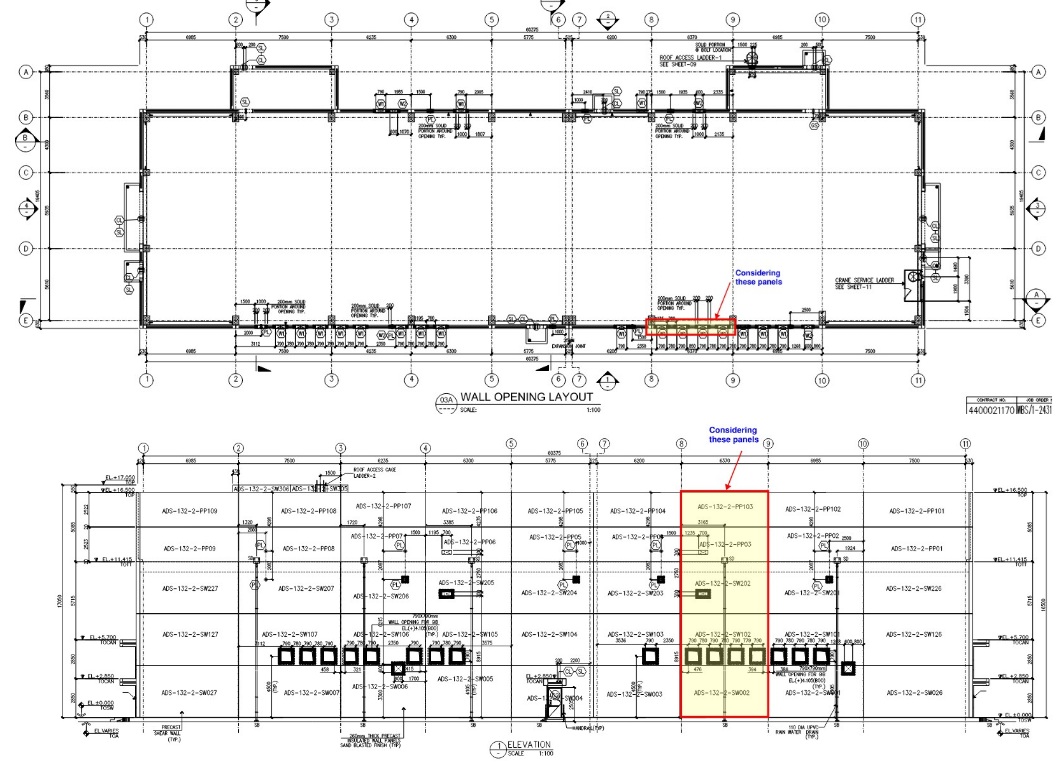
Figure 1: Cladding Panel Layout and Geometry
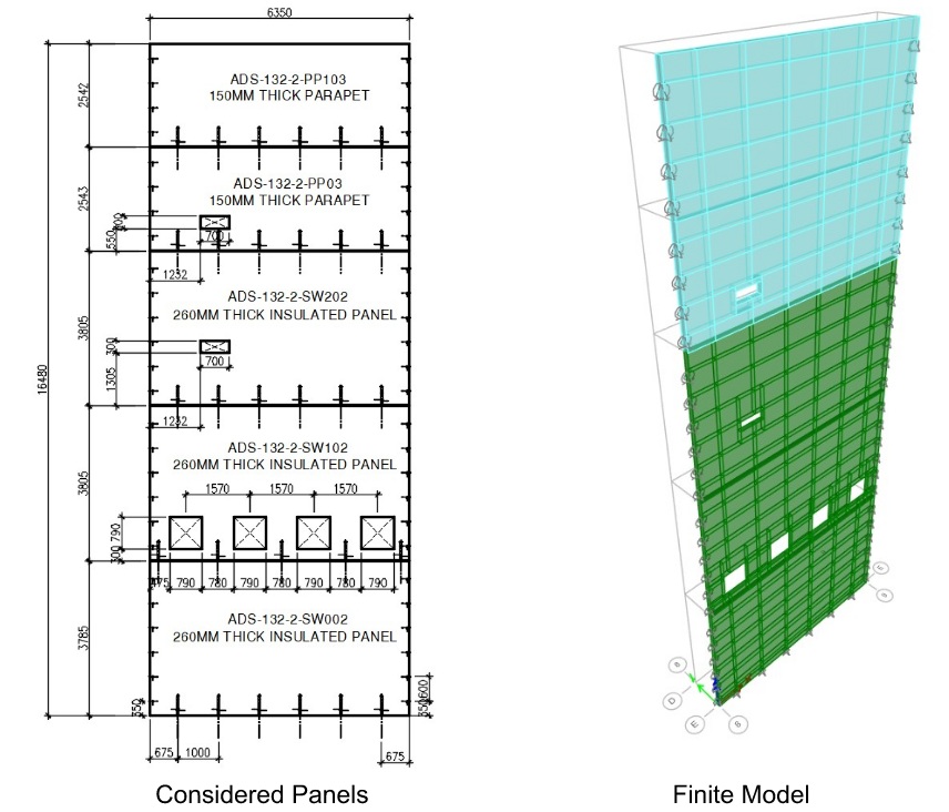
Figure 2: Panel Details and Finite Element Model
- Parapet thickness: 150 mm
- Insulated panels: 260 mm total thickness, modeled using 110 mm bearing thickness
- Façade panels: 60 mm thickness (not modeled as structural elements)
- Surface gravity load: 1.5 kPa for façade panel weight
Boundary Conditions
The panel elements are supported with the following boundary conditions:
- Base supports: Pinned supports spaced at 1000 mm c/c to simulate dowel action
- Side restraints: Z-axis (vertical) and Y-axis (horizontal) restraints at 600 mm c/c
- PVL loop connection: Only Y-axis translation (U2) restrained for conservative analysis
Load Combinations
The following load combinations are analyzed in ETABS:
- 1.4D
- 1.2D + 1.0WLy+
- 1.2D + 1.0WLy-
- 1.2D + 0.5WLy+
- 1.2D + 0.5WLy-
- 0.9D + 1.0WLy+
- 0.9D + 1.0WLy-
Where: D = dead loads, WLy+ = windward (toward), WLy- = suction (away)
Applied Loads
Considered loads are dead loads and wind loads only.
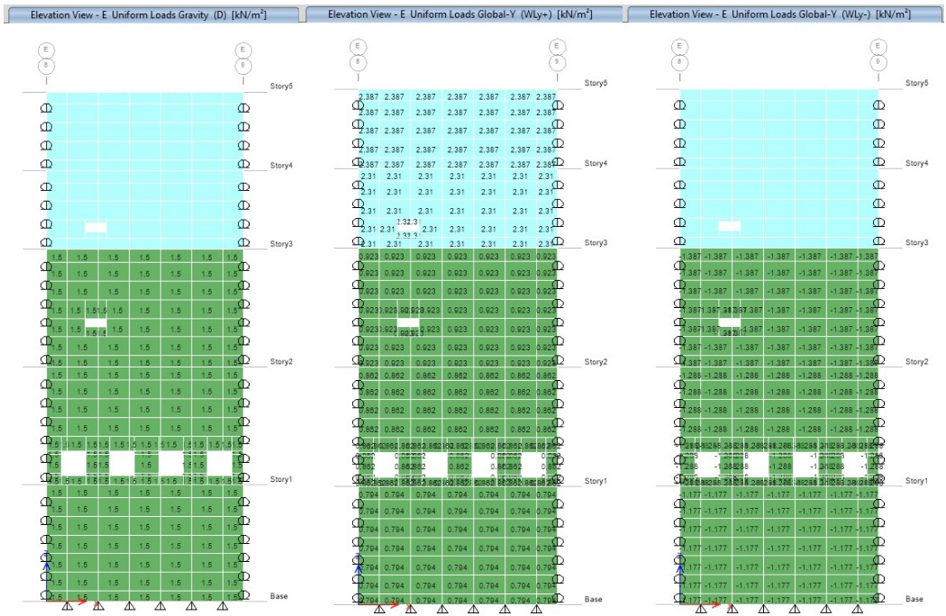
Figure 3: Applied Loads
Stress Analysis
ETABS provides stress contours for the following stress components:
- S11: In-plane normal stress along local 1-axis
- S22: In-plane normal stress along local 2-axis
- S12: In-plane shear stress
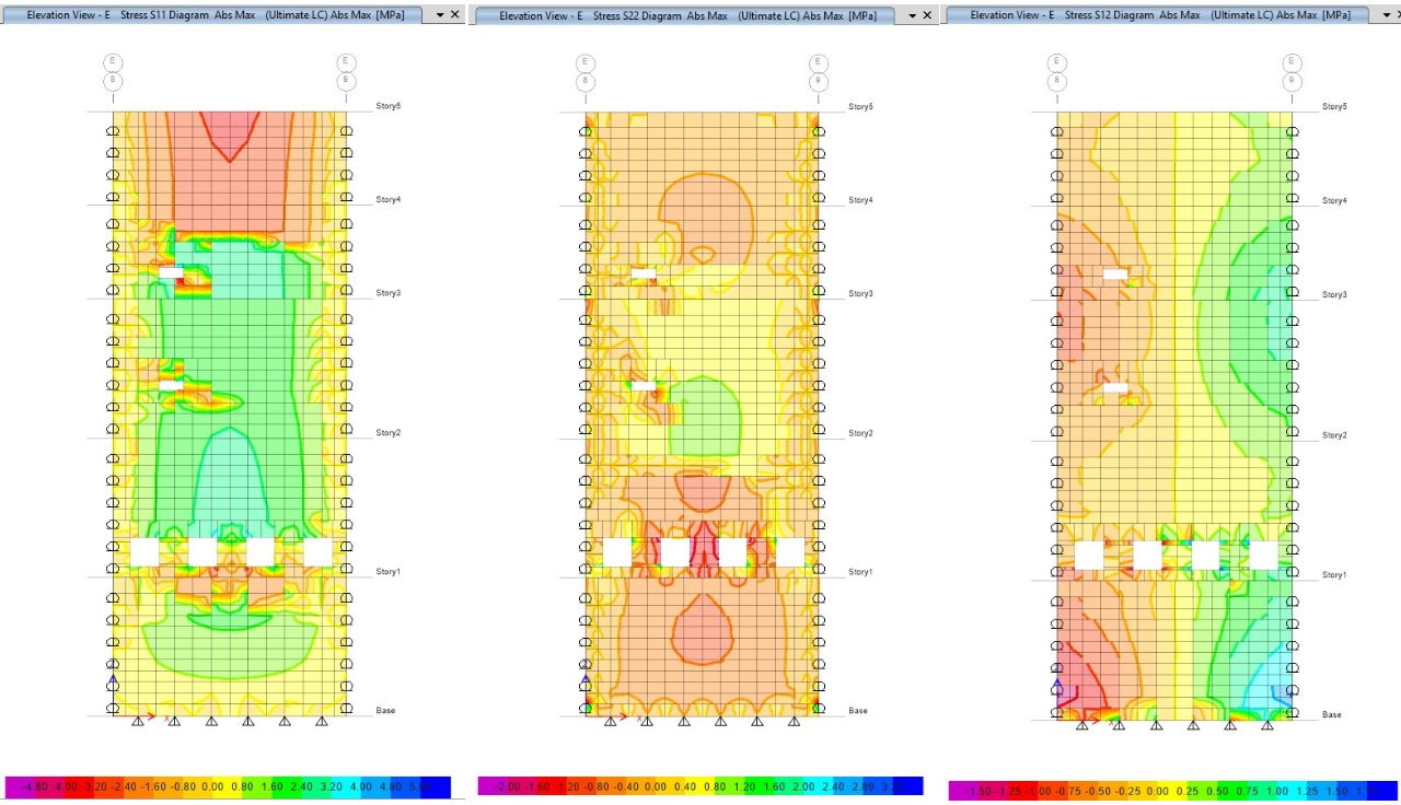
Figure 4: Cladding Panel Stresses Contours
C. Reinforcement Design Calculations
1. Insulated Wall Reinforcement
Based on ETABS analysis results, the required reinforcement for insulated walls is calculated:
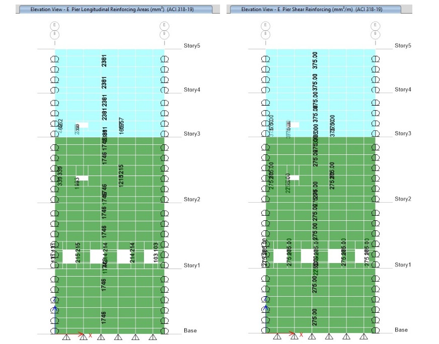
Figure 5: Required Reinforcement
Required Reinforcement (Insulated Wall)
// Required vertical reinforcement
≔Aiwv_req = 1746 mm²
≔Liwv = 6.35 m = 6350 mm
≔Aiwv_req1 = Aiwv_req / Liwv = 274.96 mm²/m

// Required horizontal reinforcement
≔Aiwh_req = 275 mm²/m
≔Liwh = 3.785 m = 3785 mm

// Provided reinforcement
≔diaiwh_used = 8 mm
≔siwh_used = 0.2 m
≔diaiwv_used = 8 mm
≔siwv_used = 0.2 m

// Provided area calculations
≔Aiwh_prov = (0.25·π·diaiwh_used²) / siwh_used = 251.33 mm²/m
≔Aiwv_prov = (0.25·π·diaiwv_used²) / siwv_used = 251.33 mm²/m

// Additional reinforcement required
≔Aiwh_add = Aiwh_req − Aiwh_prov = 23.67 mm²/m
≔Aiwv_add = Aiwv_req1 − Aiwv_prov = 23.63 mm²/m

// Additional bar spacing
≔diaiwh_add = 10 mm
≔diaiwv_add = 10 mm
≔siwh_add = (0.25·π·diaiwh_add²) / Aiwh_add = 3317.75 mm
≔siwv_add = (0.25·π·diaiwv_add²) / Aiwv_add = 3323.28 mm

// Number of additional bars
≔qtyiwh_add = Liwh / siwh_add = 1.14 → sayhi = ceil(qtyiwh_add) = 2
≔qtyiwv_add = Liwv / siwv_add = 1.91 → sayvi = ceil(qtyiwv_add) = 2
2. Parapet Wall Reinforcement
Similar calculations for parapet wall reinforcement:
Required Reinforcement (Parapet Wall)
// Required vertical reinforcement
≔Apwv_req = 2381 mm²
≔Lpwv = 6.35 m = 6350 mm
≔Apwv_req1 = Apwv_req / Lpwv = 374.96 mm²/m

// Required horizontal reinforcement
≔Apwh_req = 375 mm²/m
≔Lpwh = 2.543 m = 2543 mm

// Provided reinforcement
≔diapwh_used = 10 mm
≔spwh_used = 0.2 m
≔diapwv_used = 10 mm
≔spwv_used = 0.2 m

// Provided area calculations
≔Apwh_prov = (0.25·π·diapwh_used²) / spwh_used = 392.7 mm²/m
≔Apwv_prov = (0.25·π·diapwv_used²) / spwv_used = 392.7 mm²/m

// Design capacity ratio checks
≔DCRpwh = if(Apwh_req / Apwh_prov < 1, "Additional bar is not required.", "Provide additional bar.")
→ "Additional bar is not required."

≔DCRpwv = if(Apwv_req1 / Apwv_prov < 1, "Additional bar is not required.", "Provide additional bar.")
→ "Additional bar is not required."
D. Dowel/Anchorage Bar Design
Input Parameters
The dowel design is based on the following parameters:
Dowel Design Inputs
// Material properties
≔diadowel = 20 mm
≔f'c = 40 MPa
≔Fy = 420 MPa

// Geometry
≔sdowel = 1000 mm

// Maximum forces from ETABS analysis
≔Fxmax = −3.65 kN
≔Fymax = 3.84 kN
≔Fzmax = 88.53 kN
Capacity Calculations
The dowel capacity is verified for tension, compression, and shear:
Dowel Capacity Verification
// 1. Tensile capacity of steel
As = 0.25·π·(diadowel)² = 314.16 mm²
φt = 0.9
Pt_cap = φt·As·Fy = 118.75 kN
Pt_actual = 0 (since Fzmax > 0 → compression)
DCRtension = if(Pt_actual / Pt_cap < 1, "Pt_cap > Pt_actual, thus OK!", "Pt_cap < Pt_actual, thus NOT OK!")
→ OK

// 2. Compression capacity of steel
φc = 0.8
Pc_cap = φc·(0.85·As·Fy) = 89.72 kN
Check: Fzmax = 88.53 kN → DCRcompression = Fzmax / Pc_cap < 1 → OK

// 3. Shear capacity of the bar (dowel action)
φs = 0.75
Fxymax = max(|Fxmax|, |Fymax|) = 3.84 kN
Vcap = φs·(0.60·As·Fy) = 59.38 kN
DCRshear = Fxymax / Vcap < 1 → OK
Development Length Calculations
Development length requirements are calculated according to ACI 318M-14:
Development Length Requirements
// Material properties
Fy = 420 MPa    diadowel = 20 mm    f'c = 40 MPa    γ = 1.0

// Compression - Straight (ACI 318M-14 Eq. 25.4.3.1)
ldhc = max{ (0.24·fy·diadowel·γ / √f'c), 0.043·fy·diadowel, 200 mm } = 361 mm

// Tension - Straight (ACI 318M-14 Table 25.4.2.2)
ldht = max{ (fy·diadowel·1.7·γ / √f'c), 300 mm } = 781 mm

// Tension - 90° Standard Hook (ACI 318M-14 Table 25.3.1)
ldh = max{ (0.24·fy·diadowel·γ / √f'c), 8·diadowel, 150 mm } = 318.76 mm
→ say ldh = 350 mm

// Hook geometry
bend90 = 6·diadowel = 120 mm
lext   = 12·diadowel = 240 mm → say lext = 350 mm
E. PVL Loop Connection Capacity Check
Input Parameters
The PVL loop connection is analyzed with the following parameters:
PVL Loop Connection Inputs
// Material and geometric properties
f'cwall = 35 MPa, Fy = 420 MPa
tw = 260 mm, H = 3785 mm, spvl = 600 mm

// Applied forces (per pair connection)
VEd_parallel(per 2 loops) = 2 × 12.29 = 24.58 kN (vertical, along joint)
VEd_perpendicular(per 2 loops) = 2 × 9.56 = 19.12 kN (transverse, across joint)

// Connection type
Type = PVL80 (uses PVL60–120 tables)
Assume smooth joint (gives higher Vrd_perpendicular)
Capacity Verification
The connection capacity is verified using manufacturer tables and design codes:
PVL Loop Connection Verification
// Capacities per pair (PVL60–120, C35/45)
VRd_pair_parallel = 19.40 kN
VRd_pair_perpendicular = 21.00 kN

// Number of pairs
n = floor(H / spvl) − 1 = 5 pcs

// Total resistance
ΣVRd_pair_parallel = n · VRd_pair_parallel = 97 kN
ΣVRd_pair_perpendicular = n · VRd_pair_perpendicular = 105 kN

// Verification (ULS)
U = (VEd_parallel / ΣVRd_pair_parallel) + (VEd_perpendicular / ΣVRd_pair_perpendicular)
U = 0.44 < 1.0 → OK
Design Summary and Conclusions
Design Verification Results
Insulated Wall: Additional reinforcement required (2 bars each direction)
Parapet Wall: Provided reinforcement sufficient
Dowel Connection: All capacity checks passed
PVL Loop Connection: Utilization ratio 0.44 < 1.0 (OK)
Key Design Features
- Finite Element Analysis: ETABS modeling with shell elements and proper boundary conditions
- Load Combinations: Comprehensive wind load analysis with multiple load cases
- Reinforcement Design: Mathcad calculations for required vs. provided reinforcement
- Connection Design: Dowel and PVL loop connection capacity verification
- Code Compliance: ACI 318M-14 development length requirements
Design Methodology
This design approach demonstrates the integration of finite element analysis (ETABS) with detailed structural calculations (Mathcad) to ensure comprehensive design verification. The methodology includes:
- ETABS modeling with realistic boundary conditions and load applications
- Stress analysis and reinforcement requirement determination
- Mathcad calculations for reinforcement design and connection capacity
- Code compliance verification for development lengths and connection details
- Final design verification with utilization ratio checks
Software Integration
ETABS: CSI ETABS - Finite element analysis and modeling
Mathcad: PTC Mathcad - Structural calculations and design verification
Design Codes: ACI 318M-14, Manufacturer connection tables
Comments
Loading comments...
Leave a Comment